|
- The permissible tractive forces mentioned above refer to straight channels.
- For sinuous channels, the values of permissible tractive force should be lowered to reduce scour.
- A 10% reduction is recommended for slightly sinuous channels,
25% for moderately sinuous, and 40% for very sinuous.
STEPS IN PERMISSIBLE TRACTIVE FORCE METHOD.
- Assume b/y = 6 and z, with Q, S, and n known.
- Assume tractive force on sides is critical (as opposed to tractive force on level ground).
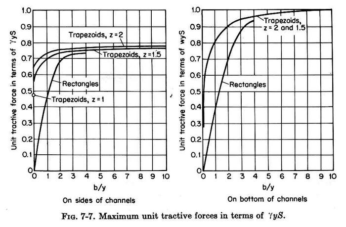
- With b/y and z, enter Fig. 7-7 left to determine Cs
in the acting unit tractive force on the sides Ts:
Ts = CsγyS
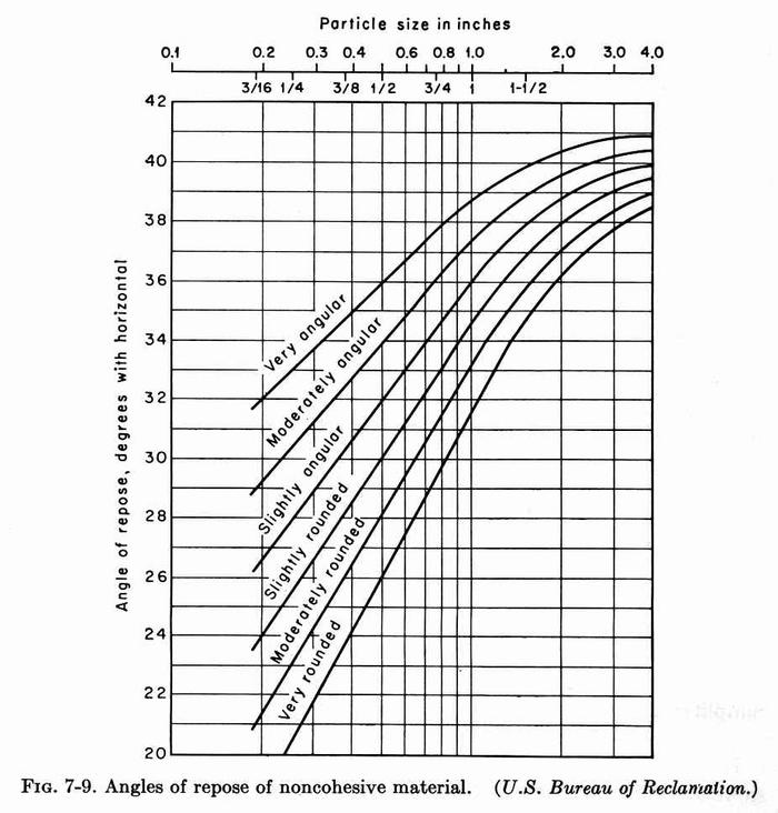
- With d25 and grain shape, find angle of repose θ from Fig. 7-9.
- Calculate φ from:
tanφ = 1/z
- Calculate K from:
K = [1 - (sin2φ/sin2θ)]1/2
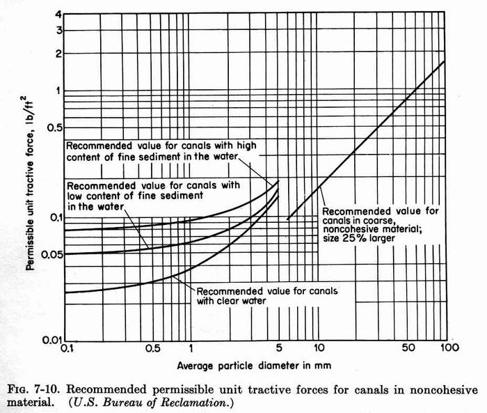
- Determine permissible unit tractive force on level ground τL from Fig. 7-10.
(If the material differs from sides and bottom,
this could be either τLb based on the material on the bottom,
or τLs based on the material on the sides).
- Calculate the permissible unit tractive force on the sides:
τs = K τL
[or: τs = K τLs]
- Set permissible and acting unit tractive forces equal: τs = Ts
τs = CsγyS
- Solve for flow depth y:
y = τs/(CsγS)
- With y and b/y, calculate b = y (b/y)
- With Q, b, z, S, and n known, design channel to find yn.
- Test to confirm that: yn ≤ y
If not satisfied, assumed b/y is too small. Assume a greater value and return to step 11.
If satisfied: y = yn
- Once b/y is determined by trial and error, enter Fig. 7-7 to
determine Cb
in the acting unit tractive force on the
bottom TL:
TL = CbγyS
- Calculate TL = CbγynS
- Compare acting unit tractive force TL with permissible unit tractive force on level ground τL calculated in step 7. [OR: with τLb if different materials]
If TL ≤ τL(b), the sides control the design.
The design is OK.
If TL > τL(b), the bottom controls the design.
In this case, make TL = τL(b).
Then recalculate yn = τL(b) / (CbγS)
- With new yn and b/y, recalculate b and confirm yn with
ONLINECHANNEL01.
Otherwise, assume new b/y until yn calculated with ONLINECHANNEL01 agrees with yn in previous step.
PERMISSIBLE TRACTIVE FORCE METHOD: EXAMPLE A (sides and bottom are the same)
Given: Q = 600 cfs; b = ?; z = 2; S= 0.001; n = 0.022; sides and bottom: noncohesive material, slightly angular,
d25 = 0.7 in.
- Assume b/y = 6.
- Assume tractive force on sides is critical (as opposed to tractive force on level ground).
- With b/y and z, enter Fig. 7-7 left to determine Cs = 0.78.
- With d25 and grain shape, find angle of repose θ from Fig. 7-9:
θ = 34o.
- Calculate φ from:
tanφ = 1/z φ = tan-1 (1/z) = 26.656o.
- Calculate K from:
K = [1 - (sin2φ/sin2θ)]1/2 = 0.6
- Determine permissible unit tractive force on level ground τL from Fig. 7-10.
τL = 0.4 × d25 (in) = 0.4 × 0.7 = 0.28 psf.
- Calculate the permissible unit tractive force on the sides:
τs = K τL = 0.6 × 0.28 = 0.168 psf.
- Set permissible and acting unit tractive forces equal: τs = Ts
τs = 0.168 = CsγyS = 0.78 × 62.4 × y × 0.001
- Solve for flow depth y:
y = τs/(CsγS) = 0.168 / (0.78 × 62.4 × 0.001) = 3.45 ft.
- With y and b/y, calculate b = y (b/y) = 3.45 × 6 = 20.7 ft. Assume b = 21 ft.
- With Q = 600, b = 21, z = 2, S = 0.001, and n = 0.022 known, use
ONLINECHANNEL01 to find yn = 4.356 ft.
- Test to confirm that: yn = 4.356 > y = 3.45. Normal depth too high!
If not satisfied, assumed b/y is too small. Assume a greater value and return to step 11.
-
Assume b/y = 8. Then b = 27.6 ≅ 28 ft.
With Q = 600, b = 28, z = 2, S = 0.001, and n = 0.022 known, use
ONLINECHANNEL01 to find yn = 3.793 > y = 3.45. Normal depth still too high!
-
Assume b/y = 10. Then b = 34.5 ≅ 35 ft.
With Q = 600, b = 35, z = 2, S = 0.001, and n = 0.022 known, use
ONLINECHANNEL01 to find yn = 3.376 ft.
Test to confirm that: yn = 3.376 < y = 3.45. Normal depth now OK!
- With b/y = 10, enter Fig. 7-7 to
determine Cb = 1.0
- Calculate TL = CbγynS = 1.0 × 62.4 × 3.376 × 0.001 = 0.211 psf.
- Compare acting unit tractive force TL with permissible unit tractive force on level ground τL calculated in step 7.
TL = 0.211 < τL = 0.28. Therefore, the sides control the design.
The design is OK.
PERMISSIBLE TRACTIVE FORCE METHOD: EXAMPLE B (sides and bottom are different)
Given: Q = 600 cfs; b = ?; z = 2; S= 0.001; n = 0.022;
sides: noncohesive material, slightly angular, d25 = 0.7 in;
bottom: noncohesive material, with d50 = 0.8 mm, with high content of fine sediment in the water.
- Assume b/y = 6.
- Assume tractive force on sides is critical (as opposed to tractive force on level ground).
- With b/y and z, enter Fig. 7-7 left to determine Cs = 0.78.
- With d25 and grain shape, find angle of repose θ from Fig. 7-9:
θ = 34o.
- Calculate φ from:
tanφ = 1/z φ = tan-1 (1/z) = 26.656o.
- Calculate K from:
K = [1 - (sin2φ/sin2θ)]1/2 = 0.6
- Determine permissible unit tractive force on level ground τL from Fig. 7-10.
τLs = 0.4 × d25 (in) = 0.4 × 0.7 = 0.28 psf.
τLb = 0.09 psf.
- Calculate the permissible unit tractive force on the sides:
τs = K τLs = 0.6 × 0.28 = 0.168 psf.
- Set permissible and acting unit tractive forces equal: τs = Ts
τs = 0.168 = CsγyS = 0.78 × 62.4 × y × 0.001
- Solve for flow depth y:
y = τs/(CsγS) = 0.168 / (0.78 × 62.4 × 0.001) = 3.45 ft.
- With y and b/y, calculate b = y (b/y) = 3.45 × 6 = 20.7 ft. Assume b = 21 ft.
- With Q = 600, b = 21, z = 2, S = 0.001, and n = 0.022 known, use
ONLINECHANNEL01 to find yn = 4.356 ft.
- Test to confirm that: yn = 4.356 > y = 3.45. Normal depth too high!
If not satisfied, assumed b/y is too small. Assume a greater value and return to step 11.
-
Assume b/y = 10. Then b = 34.5 ≅ 35 ft.
With Q = 600, b = 35, z = 2, S = 0.001, and n = 0.022 known, use
ONLINECHANNEL01 to find yn = 3.376 ft.
Test to confirm that: yn = 3.376 < y = 3.45. Normal depth now OK!
- With b/y = 10, enter Fig. 7-7 to
determine Cb = 1.0
- Calculate TL = CbγynS = 1.0 × 62.4 × 3.376 × 0.001 = 0.211 psf.
- Compare acting unit tractive force TL with permissible unit tractive force on level ground τL calculated in step 7.
TL = 0.211 > τLb = 0.09. Therefore, the bottom controls the design.
The design is not OK.
- Force TL = 0.09. Then: 0.09 = CbγynS = 1.0 × 62.4 × yn × 0.001
Solve for new yn: yn = 0.09/(1.0 × 62.4 × 0.001) = 1.44 ft.
- Solve for new b by trial and error:
- Assume b/y = 60; b = 86.4; say 87 ft.
With Q = 600, b = 87, z = 2, S = 0.001, and n = 0.022 known, use
ONLINECHANNEL01 to find yn = 2.01 ft. Too high.
- Assume b/y = 100; b = 144 ft.
With Q = 600, b = 144, z = 2, S = 0.001, and n = 0.022 known, use
ONLINECHANNEL01 to find yn = 1.49 ft. Still too high.
- Assume b/y = 106; b = 152 ft.
With Q = 600, b = 152, z = 2, S = 0.001, and n = 0.022 known, use
ONLINECHANNEL01 to find yn = 1.44 ft. OK!
|