|
Online Standard Suppressed Rectangular Weir Calculator
131103
The program online_standard_suppressed_rectangular
calculates the
discharge through a standard suppressed rectangular weir.
A standard suppressed rectangular weir has a horizontal crest that crosses the full channel width.
The elevation of the crest is high enough to assure full bottom crest contraction of
the nappe. The vertical sidewalls of the approach channel continue downstream past
the weir plate, to prevent side contraction or lateral expansion of the overflow jet.
The computation procedure follows Section 10 of Chapter 7 of
the USBR Water Measurement Manual.
Special care must be taken to secure proper aeration beneath
the overflowing sheet at the crest. Aeration is usually accomplished by placing vents
on both sides of the weir box under the nappe.
Other conditions for accuracy of measurement for this type of weir
are generally the same as for those of the contracted rectangular weir,
except for the absence of side contraction. However,
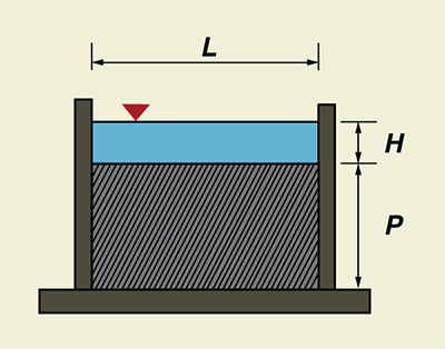
the crest height P should be at least 3H.
Fig. 1 Definition sketch for a standard suppressed rectangular weir. The formula for the standard suppressed rectangular weir is the Francis equation. In U.S. Customary units, this equation is:
in which Q = discharge, in cfs, L = length of the weir crest, in ft, and H = head on the weir crest, in ft.
The accuracy of the discharge coefficient is Equation 1 has a constant discharge coefficient (3.33), which facilitates computations. However, the coefficient does not remain constant for a ratio of head-to-crest H/L > 1/3, and the actual discharge exceeds that given by the equation. Francis' experiments were made on comparatively long weirs, most of them with crest length L = 10 ft and heads in the range 0.4 ft ≤ H ≤ 1.6 ft. Thus, the equation applies particularly to such conditions. USBR experiments on 6-in, 1-ft, and 2-ft weirs has shown that the Francis equation also applies fairly well to shorter crest lengths L, provided H/L ≤ 1/3.
No extensive tests have been made to determine the applicability of Eq. 1
to weirs with Equation 1 is subject to the following restrictions:
The head H is measured at an upstream distance of at least 4H from the weir. The sidewalls must extend a distance of at least 0.3H downstream from the crest. The overflow jet must be adequately ventilated to the atmosphere. |
| 131103 |