1. INTRODUCTION The subject of free-surface instability has interested several researchers and practitioners, beginning with Vedernikov (1945) who developed the criterion bearing his name. The Vedernikov number V = 1 describes the condition of neutral stability, which separates stable (V < 1) from unstable (V > 1) flow (Chow 1959). While stable flow attenuates disturbances, unstable flow does not. Thus, unstable flow may promote the development of roll waves in steep channels (Ponce and Maisner, 1993). In addition, under high-Vedemikov-number flows, flood waves may steepen to the point at which they become kinematic shock waves (Lighthill and Whitham, 1955; Ponce md Windingland 1985; Porras 1994).
Craya (1952) enhanced the Vedernikov criterion by interpreting it as the ratio of relative kinematic wave celerity to relative dynamic wave celerity. Later, Liggett (1975) developed the differential equation of the stable channel, for which V = 0 for all Froude numbers (F ≤ ∞). This condition is too broad, because the maximum Froude number that can be achieved in practice is likely to be much less than ∞ (usually less than 20). Instead, a stable channel may be designed by choosing a neutral-stability Froude number Fns that is much less than ∞, such that V ≤ 1 for Froude numbers in the range 2. BACKGROUND The relative kinematic wave celerity, or relative Seddon speed (Seddon 1990), is the following:
in which v = mean velocity; and β is the exponent of the equilibrium, or normal, flow rating:
in which Q = discharge; and A = flow area.
The small-amplitude relative dynamic wave celerity, or Lagrange celerity, is the following
in which g = gravitational acceleration; and D = hydraulic depth, defined as follows:
in which T = top width. The Froude number is defined as follows (Chow 1959):
Using Eqs. 1, 3, and 5, the Vedernikov number is shown to be the following:
Equation 6 underscores the physical significance of β, or rather of β - 1, since by definition,
The Manning equation in SI inits is the following (Chow 1959):
in which v = mean velocity (v = Q/A); n = Manning roughness coefficient; R = hydraulic radius Assuming a cross-sectional shape function P = k Aδ, Eqs. 2, 7 and 8 lead to the following:
in which cdrk M = dimensionless relative kinematic wave celerity assuming Manning friction.
The cross-sectional shape is characterized by the parameter δ, which varies typically in the range Case 1: The hydraulically wide channel, for which δ = 0. In this case, the wetted perimeter is constant (P = k) and independent of the flow area (dP/dA = 0). This theoretical cross section is the asymptotic limit to all wide channels (Chow 1959). Case 2: The triangular channel, for which δ = 1/2. In this case, dP/dA = (1/2)/R. The actual shape of a triangular channel is a function of the side slope z (z horizontal : 1 vertical). Case 3: The inherently stable channel, for which δ = 1 (Ponce 1991). In this case, the hydraulic radius is a constant (R = Ro = 1/k) and the wetted perimeter is proportional to the flow area: P = k A. This theoretical cross section is the asymptotic limit to all stable channels, as defined here. From these cases, it is inferred that:
The conventional definition of the Vedernikov number (Vedernikov 1945; Chow 1959; Jolly and Yevjevich 1970) is the following:
in which:
in which b = exponent of the Reynolds number R in the frictional power law f = α R-b; and
For Manning friction, b = 1/5, and therefore x = 2/3. Given Eqs. 7, 9, and 10, the equivalence of the two definitions of the Vedemikov number (Eqs. 6 and 11) is confirmed. Furthermore, from Eqs. 6 and 7, the dimensionless relative kinematic wave celerity is recast as follows:
For V = 1, F = Fns, in which Fns is the neutral-stability Froude number. Therefore:
3. STABLE CHANNEL DESIGN Liggett (1975) derived the differential equation for the stable channel, defined as that for which δ is constant and equal to 1. We shall extend the definition of stable channel to the cases where δ is constant but less than 1. Thus, two types of stable channels can be formulated. Type 1: An unconditionally stable channel, for which δ = 1 (Liggett 1975). This is the inherently stable channel, which features cdrk = 0 and Fns = ∞, and is absolutely stable (V = 0) for all Froude numbers (F ≤ ∞) (Ponce 1991). The hydraulic radius is constant (Ro). Type 2: A conditionally stable channel, for which δ < 1. This channel features cdrk > 0 and Fns < ∞, and it is stable (V ≤ 1) for Froude numbers in the range F ≤ Fns. The hydraulic radius varies with flow depth. Because of the usual symmetry of channel sections, a half-cross-section analysis is appropriate. Hereafter, the asterisk (*) is used as a subscript to refer to half values; e.g., T* is the half top width. The differential wetted perimeter of the stable cross section is defined as follows:
in which h = flow depth. Dividing by dh, and since dA* = T* dh, then:
With Eq. 10, Eq. 17 becomes the following:
The unconditionally stable channel has δ = 1 and hydraulic radius R = Ro. Therefore:
subject to T* > Ro .
The design of a stable channel requires that the hydraulic radius (Ro) be specified at the start.
The lower subsection (of bottom width B, depth ho, and side slope z) defines the hydraulic radius Ro, on which the upper subsection is based. The parameter Ro is defined at h = ho as follows:
In addition to defining Ro, the lower subsection serves the purpose of conveying the low flows. The differential equation 19 represents a family of unconditionally stable channels, with parameter Ro. A particular solution for T* = T*o at h = ho is the following:
wich reduces to Liggett's solution (1975) for the special case of T*o = Ro as follows:
Since friction has a lower bound and cannot realistically decrease to zero, it follows that there is an upper limit to the Froude number that may be achieved in practice. Thus, a channel of constant δ may be designed to remain stable (V ≤ 1) within a specific Froude-number range F ≤ Fns, where the chosen F is not likely to be exceeded for a given design condition. For example, according to Chow (1959), a practical upper bound to the Froude number may be taken as F = 20. In this case, the corresponding cross-section parameters are cdrk = 0.05 and δ = 0.925, from Eqs. 9 and 15. The extension of Eq. 18 to the conditionally stable channel, for which δ < 1 and R varies with flow depth, leads to the following:
subject to δ T* > R.
Unlike Eq. 19, Eq. 23 cannot be integrated analytically. The shape of the upper subsection T* = The numerical integration proceeds by first selecting the shape of the lower subsection and the total channel depth hf to include lower and upper subsections. In the lower subsection, the flow depth varies in the range 0 ≤ h ≤ ho; in the upper subsection it varies in the range ho ≤ h ≤ hf. In the case of a rectangular lower subsection (z = 0), the flow depth ho and half top width T*o = B* are selected. A suitable choice of Fns enables the calculation of cdrk M and δ from Eqs. 9 and 15. The initial values are h = ho; A* = B* ho; P* = B* + ho; T* = T*o; and R = A* / P*. Equation 23 is solved from h = ho to h = hf at increments of Δh. For increased accuracy, a very small Δh is chosen, such as Δh = 0.0001 m. Values of ΔT*, ΔP*, ΔA*, P*, A*, and R are calculated at every increment, in which:
and
The values of h and T* are updated before each subsequent increment.
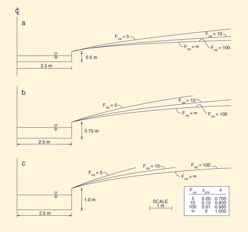
Figure 1 shows examples of stable channels calculated using the above described algorithm.
The following conclusions can be drawn from Fig. 1: (1) For a given neutral-stability Froude number Fns, the larger the initial hydraulic radius Ro, the narrower the resulting stable cross section; and These findings have significant practical implications. Given a suitable choice of Ro and Fns, a stable yet relatively narrow channel cross section may be designed following this methodology. Such a channel should be largely free from roll waves and kinematic shock waves, provided the Froude number remains in the range F ≤ Fns.
4. SUMMARY
The effect of cross-sectional shape on free-surface instability was shown to be characterized by the dimensionless relative kinematic wave celerity cdrk = β - 1, in which β is the exponent of
the equilibrium, or normal, discharge-flow area rating. Three cross-sections of constant cdrk are:
A stable channel is defined as one featuring constant δ and cdrk. Two types of stable channels are formulated: (1) unconditionally stable, for which δ = 1, cdrk = 0, and V = 0 for all Froude numbers Results show that the larger the initial hydraulic radius Ro for a given Fns, the narrower the resulting stable cross section. Likewise, the smaller the choice of Fns for a given Ro, the narrower the resulting stable cross section. Thus, given a suitable choice of Ro and Fns, a stable yet relatively narrow channel cross section may be designed. Such a channel should be largely free from roll waves and kinematic shock waves, provided the Froude number remains in the range F ≤ Fns. Additional research is necessary to experimentally verify the findings of this study. APPENDIX. REFERENCES
Chow, V. T. 1959. Open-channel hydraulics. McGraw-Hill Book Co. Inc,. New York. N.Y.
Craya, A. 1952. "The criterion of the possibility o roll wave formation."
Gravity waves, Circular No. 521, National Bureau of Standards, Washington, D. C., 141-151.
Jolly, J. P., and V. Yevjevich. (1970). "Amplification criterion of gradually varied, single peaked waves." Hydro. Paper No. 51, Colorado State University, Fort Collins, Colo.
Liggett, J. A. 1975. "Stability - Chapter 6," Unsteady flow in open channels, Vol 1. K. Mahmood and V. Yevjevich, eds., Water Resources Publications, Fort Collins, Colo., 259-281.
Lighthill, M. J. and G. B. Whitham. 1995. "On kinematic waves I: Flood movement in long rivers.: Proc. Roy. Soc. of London, Vol. A229, London, England, (May), 281-316.
Ponce, V. M. 1991. "New perspective on the Vedernikov number," Water Resour. Res., 27(7), 1777-1779.
Ponce, V. M., and M. P. Maisner. 1993. "Verification of theory of roll wave formation." J. Hydr. Engrg., ASCE, 119(6), 768-773.
Ponce, V. M., and D. Windingland, D. 1985. "Kinematic shock: Sensitivity analysis," J. Hydr. Engrg., ASCE, 114(4), 600-611.
Porras, P. J. 1994. "Flood wave propagation in inherently stable channels: Theory and applications," MS thesis, Dept. of Civil Engrg., San Diego State University, CA.
Seddon, J. 1900. "River hydraulics," ASCE Trans., Vol. 43, 179-229.
Vedernikov, V. V. 1945. "Conditions at the front of a translation wave disturbing a steady motion of a real fluid," U.S.S.R. Acad. Sciences Comptes Rendus (Doklady), Moskow, U.S.S.R., 48(4), 239-424.
|
| 211229 |
| Documents in Portable Document Format (PDF) require Adobe Acrobat Reader 5.0 or higher to view; download Adobe Acrobat Reader. |